| Back |
This is a very big section. Over the years many different types of connector (plugs and sockets) have been invented. Most are still in use!
Gold-plated connectors should be used wherever possible. As the plating is only a few atoms thick they cost little more, and they are completely free from corrosion.
The most commonly used connector is on the left and the least used on the right.
Used for |
Connector |
|---|---|
RGB |
Phono, 15 pin D, SCART adaptor, BNC |
Component |
Phono, BNC |
S-video |
4 or 7 pin mini-DIN SCART adaptor |
Composite |
Phono, SCART adaptor |
Audio |
Phono, XLR |
Loudspeakers |
4mm sockets, Neutrik, proprietary socket |
Aerials and dishes |
Coaxial, F-connector |
,
These are all described later. To jump to one click the underlined name. For permanent installations connectors are often put into flush fitting wall plates
|
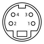
4 pin S-Video mini-DIN Male solder side |
|
4 pin S-Video mini-DIN Female solder side. This is also pin side of male plug. |
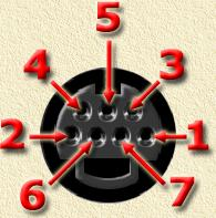 |
Seven-pin variant. View here is non-solder side female which is the same as solder side male. Three screened cores or cables are needed. |
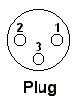
Pin |
Signal |
1 |
Y ground |
2 |
C ground |
3 |
Y Intensity Luminance |
4 |
C Colour Chrominance |
5 |
|
6 |
Composite video |
7 |
Composite ground |
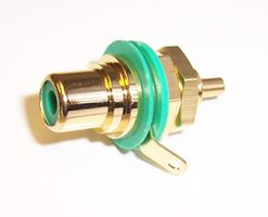
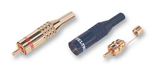
These are used for some RGB and most component video connections. Audio connections almost always use phono, though some professional installations use the XLR connector. Cable is always screened, with RG59 being commonly used for video. The centre pin or hole is for the signal lead. The braid screen is pulled to one side, twisted into a bundle then soldered to the socket tag or outer clip on the plug. It is best to insulate the braid with heat shrink tubing to avoid shorting when bending it to instal it into boxes.
Phono socket |
Phono plug |
|
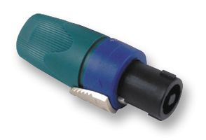
These are used for connecting loudspeakers to amplifiers in car audio and professional sound systems. They are mated by push, rotate and lock, and are very robust, though rather large. |
Seen from rear (solder) side of the socket
This is also the pin side of the plug |
Seen from rear (solder) side of the plug
|
15-pin SVGA Connector PinOut
| Pin | Pin Name | Pin Description | Usual core colour |
|---|---|---|---|
| 1 | RED Video | Red Video | Red |
| 2 | GREEN Video | Green Video | Green |
| 3 | BLUE Video | Blue Video | Blue |
| 4 | |||
| 5 | GND | Ground | Black |
| 6 | RGND | Red Ground | Red core braid |
| 7 | GGND | Green Ground | Green core braid |
| 8 | BGND | Blue Ground | Blue core braid |
| 9 | |||
| 10 | SGND | Sync Ground | Brown |
| 11 | |||
| 12 | |||
| 13 | HSYNC | Horizontal Sync | Orange |
| 14 | VSYNC | Vertical Sync | Yellow |
| 15 |
This is the most difficult connector to solder, as the pins are close together. Prepare the co-axial cores first, using narrow heat-shrink sleeving to ensure the braids don't short out anything. Solder the R, G and B cores and screens first, then the four small single cores. The cable screen is usually connected to the metal body of the connector. This can be done by soldering it to a tag held down by one of the mounting screws, again using heat-shrink sleeving.You can buy wallplates that have screw terminals, with the connector attached to a circuit board so no soldering is needed.
Pins 4, 9, 11, 12, 15
If used, these are for computers only
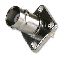
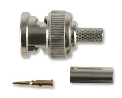
These are occasionally used for video or audio connections. They are stronger and have the advantage that the plug is locked into place by rotating the knurled ring. The centre pin or hole is for the signal lead. The braid screen is peeled back and locked or soldered to the body of the connector. The solder-on plugs are quite difficult to fit, so crimp-on types are often used. BNC connectors are available in both 50 and 75 ohm impedances, though using the wrong one generally makes little difference.
BNC socket |
BNC crimp plug
|
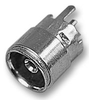
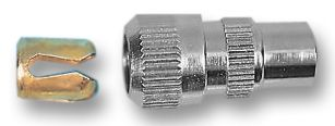
These are used in the UK for UHF TV and VHF radio aerial (antenna) connections. Co-axial cable is used and is prepared in a very similar way to that shown for F-plugs. The difference is that the centre conductor is left longer and is pushed into a hollow centre pin and usually soldered at the tip. The turned back braid is gripped by the piece of metal shown outside the plug below. The end cap is then screwed down onto it and the narrower part of the plug.
Co-axial socket (usually on the equipment chassis)
|
Co-axial plug
|
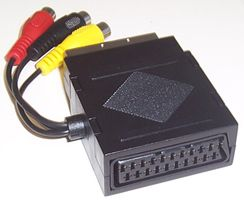
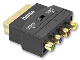
The name is sometimes said to mean 'Some Connectors Are Really Tinny'. The connector was designed to cover all possible connections. It cannot carry all of them at the same time, as some pins have more than one function. For this reason there cannot be a single pin-out diagram. Few installers like them as they are easily dislodged and for some unknown reason the sound disconnects last, leaving you baffled as to why the picture has gone. They are also large and clumsy.
|
It is best to buy high quality SCART cables. Because of the large number of cores, these are likely to be thick and inflexible. Look for 'fully connected' and 'separately shielded signals'.
|
 |
 |
|---|
| Output connector |
Input connector |
||
|---|---|---|---|
1 |
Audio right out |
2 |
Audio right in |
3 |
Audio left (or mono) out |
6 |
Audio left (or mono) in |
4 |
Audio return |
4 |
Audio return |
7 |
Blue out |
7 |
Blue in |
5 |
Blue return |
5 |
Blue return |
11 |
Green out |
11 |
Green in |
9 |
Green return |
9 |
Green return |
15 |
Red out |
15 |
Red in |
13 |
Red return |
13 |
Red return |
16 |
RGB status out |
16 |
RGB status in |
14 |
RGB status return |
14 |
RGB status return |
19 |
Sync (composite video) out |
20 |
Sync (composite video) in |
17 |
Sync return |
18 |
Sync return |
21 |
Shield |
21 |
Shield |
| Output connector |
Input connector |
||
|---|---|---|---|
1 |
Audio right out |
2 |
Audio right in |
3 |
Audio left (or mono) out |
6 |
Audio left (or mono) in |
4 |
Audio return |
4 |
Audio return |
15 |
Chrominance out |
15 |
Chrominance in |
13 |
Chrominance return |
13 |
Chrominance return |
8 |
Video status out |
8 |
Video status in |
19 |
Luminance out |
20 |
Luminance in |
17 |
Luminance return |
18 |
Luminance return |
21 |
Shield |
21 |
Shield |
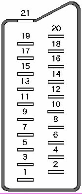
Composite Video Connection
| Output connector |
Input connector |
||
|---|---|---|---|
1 |
Audio right out |
2 |
Audio right in |
3 |
Audio left (or mono) out |
6 |
Audio left (or mono) in |
4 |
Audio return |
4 |
Audio return |
8 |
Video status out |
8 |
Video status in |
19 |
Composite video out |
20 |
Composite video in |
17 |
Composite video return |
18 |
Composite video return |
21 |
Shield |
21 |
Shield |
(Composite) Decoder Connection
| Receiver connector |
Decoder connector |
||
|---|---|---|---|
1 |
Audio right out |
2 |
Audio right in |
2 |
Audio right in |
1 |
Audio right out |
3 |
Audio left out |
6 |
Audio left in |
6 |
Audio left in |
3 |
Audio left out |
4 |
Audio return |
4 |
Audio return |
8 |
Video status in |
8 |
Video status out |
19 |
Baseband out (scrambled) |
20 |
Baseband in |
17 |
Baseband out return |
18 |
Baseband in return |
20 |
Composite video in (unscrambled) |
19 |
Composite video out |
18 |
Composite video in return |
17 |
Composite video out return |
21 |
Shield |
21 |
Shield |
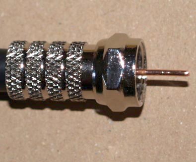
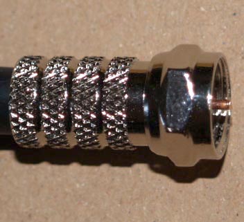
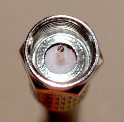
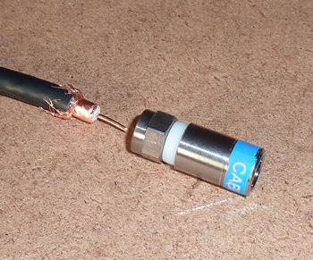
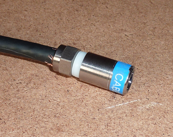
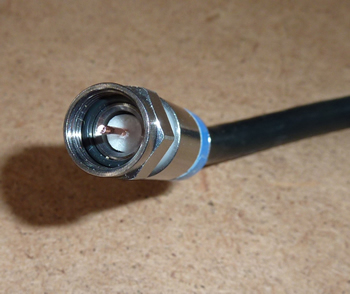
These are used widely in the USA for aerial (antenna) connections, and are now increasingly used everywhere for satellite cable connections. As they screw on to the sockets, F plugs can't come loose. The impedance is 75 ohm and it can handle frequencies up to 3 GHz. The main criticism of them is that the bare copper core, used as the signal pin, can become corroded and make poor connection, though this does not seem to happen in practice if they are properly sealed against water using tape, rubber boots or silicone. The de-luxe version is the crimp-on F-connector, which is fitted using a crimp tool and is fully sealed against water. Naturally these are much expensive, but worth it for outside use. You can buy gold-plated plugs, but these often need soldering on. This removes one of the major advantages, which is that you can fit them without having to do any soldering.
Fitting an F-connector
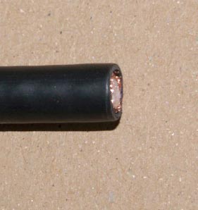 |
WF100 cable cut square. |
|---|---|
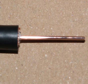 |
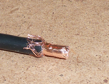
Trim off about 15 mm of the cable down to the core. |
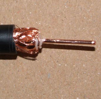 |
Trim off about 5 mm of the outer sheath, taking care not to cut through the braid. |
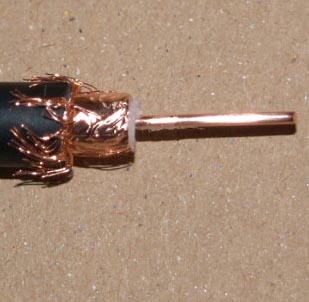 |
Fold back the braid. |
 |
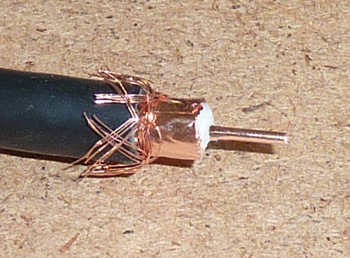
Screw on the F connector. |
 |
Trim the core so that it sticks out about 2 mm. |
 |
This is how far the connector should be screwed on. |
A selection of F adaptors
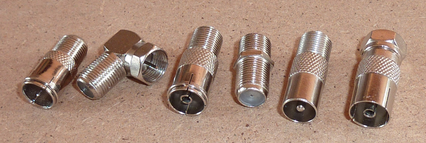
You can buy an adaptor with an F plug or socket at one end and a standard UK coax plug or socket at the other. To extend F cables you can get connectors with an F socket on each side. F connectors and cables stick out from the back of equipment and from wallplates. I now use right-angle adaptors, which allow the cable to run parallel and so closer in. The downside of using adaptors is that each connector drops the signal slightly.
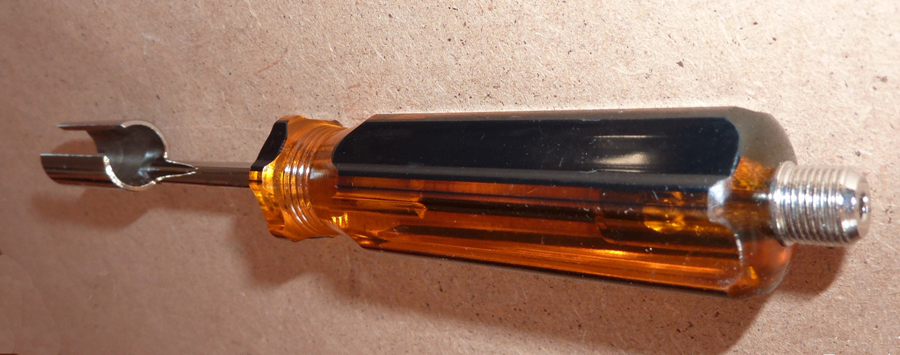
Where F-plugs are fitted close together it can be difficult to tighten them with your fingers. An 11mm spanner, with the sides ground down as narrow as possible, can help, or you can buy a box spanner like the one below, designed for the job, that has a slit in its side to allow it to be slipped on. You screw the rotatable part of an F plug on to the threaded part of the spanner to make it easier to screw it on to the cable.
This is how to use the Webro crimp F plugs and hand tool
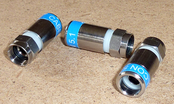 |
These are the Webro crimp connectors. |
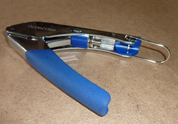 |
This is the hand tool. |
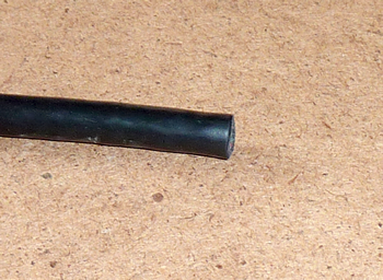 |
Prepare the WF100 cable. |
 |
Strip the outer sheath back to 13 mm and trim the braid back to about 7 mm. |
 |
Trim the foam dielectric to about 7 mm without damaging the copper screen. This is best done by only pushing the blade inwards from several directions. If you twist the cable it will tend to tear the copper. |
 |
Reverse the plug so the screw end is facing the cable. |
 |
Slide the plug on to the cable to prepare the copper screening foil. |
 |
Turn the crimp plug the right way round and ease and twist it on until the dielectric is in the correct place. Finally trim the centre copper core, if necessary, so it sticks out 1 or 2 mm. |
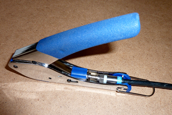 |
Lay the plug and cable in the tool and squeeze the handles together. |
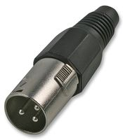
The name XLR comes from eXternal, Live, Return. It is an audio connector mostly used by professionals. However it is found on some high quality home audio equipment, such as Cyrus amplifiers and CD players. The connectors are robust and they lock in place. However they are much larger than phono plugs. For best results a screened twin-core cable is used. Two cores are used for the audio signal out and return on pins 2 and 3. The screen braid is not connected to the signal cables and is attached to pin 1. The signal cores are twisted giving excellent rejection of interference. This is known as a balanced connection. When XLR is used at one end of the cable and a phono connector is at the other, pins 1 and 3 are both connected to the screen and the single signal core connected to pin 2. This is called unbalanced. The outgoing signal travels in the direction of the connector pins. Therefore a female socket on equipment shows that this is an input.
XLR connectors
Solder side |
Solder side |
|
Balanced Audio (3 pole XLR): Pin
1: Ground / Screen |
Unbalanced Audio (3 pole XLR): Pin
1: Ground / Screen |
 |
 |
|---|---|
Plug |
Socket |
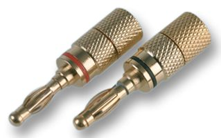
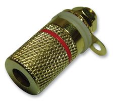
These are often used for loudspeaker connections and are sometimes called 'banana plugs'. The larger size is needed where high audio powers are used, as currents can be high and cables need to be large. Some connectors have a screw fitting but probably the most reliable is where the cables are soldered
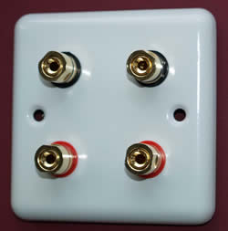
A wall plate is a metal front the same size as a single or double mains socket. Instead of sockets it has one or more of the connectors described above. If you are making a permanent installation you might want the cables buried under the plaster of your walls. This would apply, for example, if you were connecting to a ceiling mounted projector or to rear or side loudspeakers. Circular or oval plastic conduit makes a good pipe for the cables and you use normal metal electrical boxes. Make sure you use 47 mm deep ones to give plenty of room for the cables to bend. The boxes might need modifying for HDMI and CT100 cable. A socket box for a satellite wall plate will need one side, usually the top or bottom, almost completely removed. This allows the two CT100 cables to be very near the surface of the wall and so not need bending to enter the screened clamps. Modifications for HDMI are covered on the HDMI page.
Cutting holes for boxes and grooves for conduits is now made quicker if you use an SDS drill with a spade and a channelling chisel. There will be lots of dust and chips so put on eye protection and use a mask. Use a general purpose plaster, topped with a white filler, to refill the holes.
You can buy ready-made wall plates or make your own using metal blanking plates. It is best to use aluminium or brass plates, as the stainless or mild steel ones are much more difficult to work. Most connectors need round holes, the exceptions being the 15 pin D for SVGA and the HDMI connector. For large holes you can buy a tapered reamer to enlarge the biggest hole that you can drill. You will have better control, and so get a smoother hole, if you clamp the reamer vertically in a bench vice and turn the plate on it.
Here are two examples, one bought and one home-made.
 |
 |
It is likely that cables will be replaced by wireless connections similar to that used for computer networks.
| Back |
(C) Peter Scott 2009
Last edit 26 December 2015