| Back |
HDMI and DVI
The high-definition multimedia interface (HDMI) connection is all digital. It is a standard that includes the Digital Video Interface (DVI), multichannel high-quality audio and various control signals. Version 1.0 allows video up to 1080 progressive and is the one currently in use in domestic AV equipment. Version 1.3 allows resolutions up to 2560 by 1600 and deep colour using 48 bits instead of 24 but it requires two data channels and a bigger connector and cable. For audio there is provision for eight channels of 192 thousand samples per second and 24 bits per sample. HDMI can also handle four times the data rate needed for Super Audio Compact Disk (SACD). There are also control signals. These three types of data are sent in sequence. A Video Data Period has the data for one video line. During the times between lines and frames the audio is sent in the Data Island Period. Between these the control data is sent in the Control Period. Other clever features include lip-sync, which stops the effect sometimes seen where the sound and video are out of step on digital systems like Freeview.
This is the view from the rear (solder) side of the plug
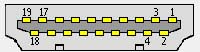
Pin |
Signal Name | Notes |
1 |
TMDS Data 2+ | This channel carries Red or Cr |
2 |
TMDS Data 2 Shield | |
3 |
TMDS Data 2- | |
4 |
TMDS Data 1+ | This channel carries Green or luminance Y |
5 |
TMDS Data 1 Shield | |
6 |
TMDS Data 1- | |
7 |
TMDS Data 0+ | This channel carries Blue or Cb |
8 |
TMDS Data 0 Shield | |
9 |
TMDS Data 0- | |
10 |
TMDS Clock+ | This channel synchronises the others |
11 |
TMDS Clock Shield | |
12 |
TMDS Clock- | |
13 |
CEC | Consumer Electronics Control: see text below |
14 |
No Connect | |
15 |
SCL/DDC Clock | Digital Display Channel: see text below |
16 |
SDA/DDC Data | |
17 |
DDC/CEC Ground | |
18 |
+5V Power | |
19 |
Hot Plug Detect | Notes when a new device is connected |
The casing is called pin 20
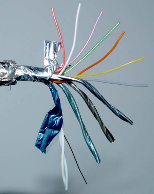
These are the core colours from a cable that I dissected. It was a surprise that the data and clock pairs each had the same pair of colours, light blue and white. There was no way of identifying which pair was which. I don't know if these are conventional colours or not, so this information might be entirely pointless.
| Pin | Core colour | Pin | Core colour |
| 1 | Light blue (pair with 3) | 2 | Bare copper (shield 1/3) |
| 3 | White (pair with 1) | 4 | Light blue (pair with 6) |
| 5 | Bare copper (shield 4/6) | 6 | White (pair with 4) |
| 7 | Light blue (pair with 9) | 8 | Bare copper (shield 7/9) |
| 9 | White (pair with 7) | 10 | Light blue (pair with 12) |
| 11 | Bare copper (shield 10/12) | 12 | White (pair with 10) |
| 13 | Green | 14 | Grey |
| 15 | Orange | 16 | Mauve |
| 17 | White | 18 | Reddy orange |
| 19 | Yellow | 20 | Outer braid connected to case |
There are three types of connector. Domestic equipment currently all uses type A, which has 19 pins. It is used for a single video channel connection, and is shown above. Type B has 29 pins and can carry twin channels to carry the data needed for high resolutions and deep colour. Type C is a miniature 19 pin connector for cameras and similar devices. The cables use screened twisted pairs of wires. Category 1 cable for normal HDMI can be used up to 5m when 28 awg cores are used, and 15m for 24 awg, but you can read more about this in the section on signal degradation below. For greater distances fibre or computer network Cat-5 cable can be used, or several normal cables end to end with the signal boosted and improved by repeaters.
Pin 13 is called CEC, for Consumer Electronics Control. This allows equipment to communicate and users to control it. It is in fact a bus network. Any piece of equipment capable of using it is able to create a map of all of the devices attached to the CEC line network. Each piece of equipment is given a four part CEC number rather like an IP address. User-control-actions each have a code which all equipment will recognise. Different manufacturers give CEC different names, for example Anynet with Samsung and Viera Link for Panasonic. CEC is also used for Content Protection, which can prevent the video or audio recordings or programmes being used if permission has not been got or paid for.
Pins 15 and 16 form the Display Data Channel. This allows pieces of equipment to exchange information about what each is capable of.
DVI is the video part of HDMI. You can buy adaptors or cables to allow you to connect one to the other. The sound will not work of course, so you would need a feed to an audio system for that.
This is a cut-away HDMI cable showing the connector and the many cores.
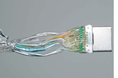
| This shows the four screened pairs and the other seven conductors |
 |
| The cores are soldered to a small board in the connector. The outer screen is bundled and soldered to the case. |
 |
HDMI wall plates all seem to have a rear socket into which a ready made HDMI plug can be pushed. It means that if the cables are to be concealed, the duct or conduit must be large enough to push a complete HDMI connector through. 22 x 12 mm oval plastic conduit should be large enough, though surplus plastic might need to be trimmed off the connector to get it through.
For HDMI I have decided not to use wall plates. Instead I run a connection lead from the device to the projector. This is good practice anyway, as connectors cause signal loss and perhaps other problems, but it is probably most important for long HDMI connections.
Modifying back boxes
If you are going to use a wall plate you will need a metal box, called a 'back box', in the wall, but it will have to be modified. The HMDI socket will have to be mounted at 90 degrees from its normal position to allow the cable to enter the box and socket vertically. Some of the box will be cut away to make room for the plug.
Criticisms of HDMI
Poor connectors
HDMI connectors are not strong. They are often surface mounted on the circuit board rather than having pins that are soldered through it. A small jolt can damage them. The plugs do not lock into the sockets so can be pulled out. The manuals that come with equipment that use HDMI all warn against possible damage. You must take care to insert the plug straight and without rocking. The cables must be supported if there is much free length. You must not push the equipment back against the back of a cabinet or a wall in case it puts pressure on the socket.
Signal degradation- cables and error detection
Critics say that the HDMI cable was specified with short, domestic connections in mind, and the needs of the industry to protect its copyright. If broadcast engineers had been consulted they would have specified co-axial cable, which would be capable of the much longer connection routes sometimes needed, for example in permanent installations like projectors. The broadcast world adopted High-Definition Serial Digital Interface, which uses a single co-axial cable and can run for a hundred metres without repeaters. With 720p and 1080i good quality HDMI cables only run reliably to about 15m with most equipment. Some combinations of equipment won't work even at this distance.
HDMI cable is not co-axial so the impedance can vary a lot. Good quality co-axial varies by no more than 2% but twisted pair is about 15%. Signals can reflect off the change points and bounce back and corrupt oncoming signals. Twisted pair used on computer networks rarely goes above 100 Mbit/s. Even gigabit networks only use 250Mbit/s. 1080i requires 742.5 Mbit/s and the progressive version is double that. What's worse is that the data for the three colour signals travel in parallel down three pairs of wires. The high data rate makes synchronising them a potential failure point. High tolerance twisted pair cables are being developed but are likely to be expensive compared with co-axial.
Overall then, with digital you either get a perfect or near perfect picture, or no picture at all. The point at which this happens depends not just on the length of the cable, but also the quality of the circuitry in the source and display equipment. Perhaps the wireless system called Flywire will solve this soon.
| Back |
(C) Peter Scott 2009
Last edit 26 December 2015