| Back |
Principles of flight
If you would like to download this document as a pdf please click here.
Left and right (port and starboard)
In an aircraft left and right are as the pilot sees looking forward.
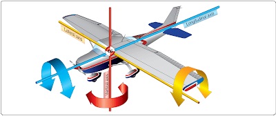
The three axes
Aircraft can rotate in three axes. The pitch axis (yellow) is where the nose rises and falls. The roll axis blue) is where one wing goes up and the other goes down. The yaw axis (red) is where the tail moves to one side or the other.
https://www.aircraftsystemstech.com/
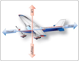
The four forces
An aircraft feels four forces. Vertically, lift pushes the aircraft upwards and weight pulls it downwards. In the direction of travel, thrust from the engine or motor pushes it forward and drag holds it back. For level flight at a constant speed thrust must equal drag and lift must equal weight. To speed up we increase thrust and to climb we increase lift by speeding up. Just using up elevator to rise will probably cause a stall.
https://www.aircraftsystemstech.com/
Balance
Centre of gravity (CofG), or centre of mass, is the point on any object through which its weight appears to act. It is the balance point. Lift also acts through a point in an aircraft. To avoid the nose pitching up or down the lift should act through the same point as the weight. However the lines of action of both weight and lift vary in flight, for example as fuel is burned off or the speed of the air over the wing varies. If the CofG is in front of the centre of lift the nose will tend to pitch down, called nose heavy. This is stable but makes the aircraft less agile. If the CofG is behind the centre of lift the nose will tend to pitch up, called tail heavy. This can make the aircraft unstable though highly skilled flyers will do this deliberately to make their models responsive. Gliders tend to have a more rearward CofG partly to balance the lift from the tailplane.
Names of flying surfaces and control surfaces
The majority of aeroplanes or aircraft are fixed wing. The word aeroplane derives from the word for air and the fact that planes are flat surfaces. The lift is created by one or more flying surfaces. The wing is usually connected to a long thing called a fuselage. Some aircraft have no fuselage (flying wing). If the wing is above, or at the top of, the fuselage it is called ‘high wing’. Similarly there are ‘low’ and ‘mid’ wings. High wings are the most inherently stable, which is why they are used on trainer models.
Most aircraft have two other flying surfaces at the rear of the fuselage, or sometimes in front (canard). The horizontal surface is called a tailplane and the vertical is called a fin. Some people call them horizontal and vertical stabilisers for no reason that I can think of.
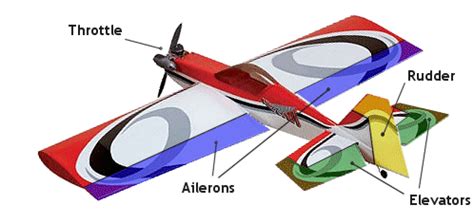
Attached to each flying surface are the three control surfaces.
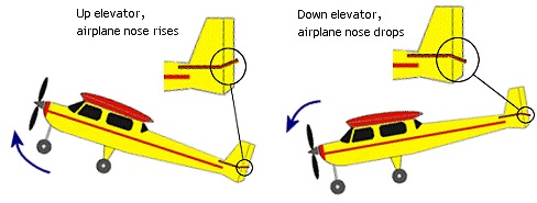
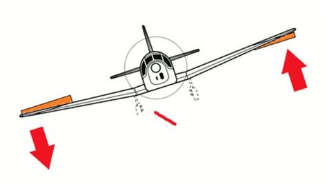
Hinged on the rears of the wings are two ailerons. These create roll, where the aircraft tips over. To roll left the left aileron goes up and the right goes down. They are normally in the outside half of the wing but are sometimes full span. Usually the ailerons also cause the aircraft to turn but not on some high performance aircraft. To yaw there is a rudder hinged on the back of the fin. The aircraft turns but does not tilt. To pitch the nose up or down there is an elevator hinged on the back of the tailplane. It is possible to fly with only two of the control surfaces, or even one, but most model aircraft have all three. The throttle varies the power that the engine or motor produces.
rc-airplane-world.com
Pitch (elevator)
rc-airplane-world.com
Yaw (rudder)
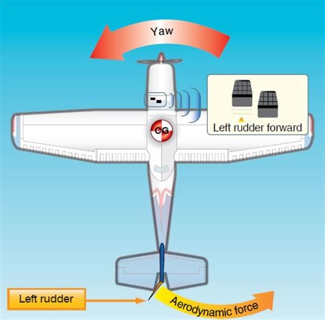
flightliteracy.com
Roll (ailerons)
Quora.com
Trim
The most risky flight for a new model is the first, or maiden, flight. The flyer can never be sure how it will fly and must be ready to make adjustments, usually in flight. This is called trimming. On full size aircraft there are smaller control surfaces called trim tabs attached to each aileron, elevator etc. These are used to adjust for air conditions and CofG position and movement. On models we can’t afford the weight and complexity so we trim using tiny movements of the main control surfaces.
Root and tip
The root of the wing is where it attaches to the fuselage. The tip is the extreme outboard end of the wing. Leading and trailing edges are obvious. The distance from tip to tip is called wingspan and the distance from leading to trailing edge is called chord (pronounced ‘cord’)
Airbrakes and flaps
Full size aircraft normally have flaps that are lowered for take-off and landing. Amongst other things they increase the lift of the wing at the slower speeds needed for landing. If you have sat near the wing of a passenger jet you will have seen the complex sets of flaps that come down for landing. In models they are usually a simple pair of flaps hinged on the rear of the wing, inboard of the ailerons.
Airbrakes are used to bring the airspeed down, usually for landing or to lose height rapidly. They are mostly used in model gliders, which might have to land on a small hillside area or which might float, when landing, from one end of the runway to the other without losing height. They either project up from the top of the wings or are a combination of opposed flap and aileron movements called ‘crow brake’.
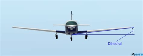
Dihedral
On many aircraft the wing tips are higher than the root. This is called dihedral. It makes an aircraft more stable but less manoevrable. When an aircraft with dihedral yaws by rudder action, the forward moving wing develops more lift and the other less. This causes roll or banking and a turn in the direction of the yaw. That is how it is possible to steer with only rudder and why aerobatic models have no dihedral, allowing accurate control of roll.
aviatir.com
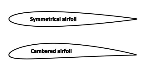
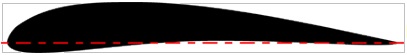
Aerofoils (or airfoils)
An aerofoil is the shape of the wing looked at in cross-section. This is an arcane subject similar to the Philosophers Stone. There is no doubt that for high performance models, especially gliders, the aerofoil is a major factor in performance. Wind tunnels are used to test them. For most ordinary models it has a modest effect. Aerobatic models usually have thick symmetrical sections. Trainers have flat bottomed sections. The difference between the curvature of the upper and lower surface is called camber. Gliders have more complex shapes often with the underside curved downwards at the rear called undercamber.
kids.kiddle.co
Undercambered
https://airfieldmodels.com/
How flying surfaces create lift
I am tempted to say, ‘Forget it and just be grateful that they do.’ You might want to skip this bit. The classic explanation is that the air has to speed up over the longer upper wing surface. This causes a drop in pressure which pulls the wing up. However as the hapless Arthur says in the first of the Cabin Pressure comedies, that means aircraft can’t fly upside down. And of course a symmetrical aerofoil cannot produce lift. I prefer an explanation based on molecular movement and collisions. My paper on the subject is listed at the end.
Telemetry
The best radio control systems allow the airborne receiver to send data back from the aircraft. Examples are airspeed, battery voltages, energy used, altitude, motor rotation speed and rate of rise or fall (variometer). This is a major strength of FrSky.
Radio control
We are blessed with superb and continuously advancing technology. My own favourite is that produced by the Chinese company FrSky (pronounced ‘freesky’). Other brands are available.
To control our models we need five things:
• a transmitter to send out our control signals and to receive telemetry data
• servos to move the control surfaces
• a receiver to control the servos and to send back the telemetry data
• linkages to connect the servos to the control surfaces
• a power supply for the receiver and servos
Type of motive power
For model aircraft there are four sources of energy. The first is gravity. Gliders can be towed up by a powered tug aircraft, a large rubber bungee line or a hand held towline. They then soar unpowered, hopefully finding thermal lift. The second is wind kinetic energy, which is pushed upward by a slope and can carry a model with it. The third is chemical energy in the form of alcohol or petroleum-based liquid fuel. There are three groups of these internal combustion (IC) engines – glow-plug, petrol and gas turbine. The fourth is electricity usually stored in lithium polymer (lipo) batteries. Electric brushless motors can produce great power under the control of an electric speed controller. As an aside, flyers of indoor models also use strands of rubber or motors using compressed carbon dioxide to drive props.
Propellors
Some gliders have no motor nor propellor. Most models have some form of propellor, made from plastic, carbon fibre or wood. Two bladed props are most efficient but three and four bladed ones are used for scale or ground clearance reasons. On gliders props usually fold back when the motor is off to reduce drag and possible damage on landing. Props are specified by two numbers that are unfortunately still usually in archaic inches. An example is 12 x 8. The first number is the diameter and the second is the pitch. The latter is the theoretical distance the propellor moves forward in one revolution. It is crucial to match the propellor to the motor or engine to get the most power and efficiency. It is also important to balance a prop so it does not vibrate.
Thrust lines
If you are flying a new model that have bought you can forget about this. If you have built or repaired a model you need to understand it. The thrust of a motor is in line with the shaft of the motor or engine. It is common to tilt the motor a few degrees to one side, or down, or both. This is so that the thrust line goes through the so-called neutral point of the model or so that the sideways turning effect of the prop can be cancelled.
My own stuff on the science
If you want to learn more about flight go to my website at peterscott.website/flying. Go into ‘Science of model flying’, then ‘Theory of flight.’ There you will see more scientific and detailed explanations of lift and drag, airfoil theory and other aerodynamic ideas. You can also download my FrSky manual to show you what the best radio control systems are capable of.
(C) Peter Scott 2021 (except pictures)
Last edit 21 December 2021
| Back |